The Interrupts
Solution the original problem with pizza delivery is very simple - when delivery man arrives with pizza, he rings the bell or knocks the customer's door. Sometimes, the customer is even notified via phone. Thus, the customer doesn’t have to worry whether the delivery time has elapsed or whether the delivery man came sooner. Customer can deal with own, more important duties, and will be automatically alerted once the delivery is to be finished.
This mechanism, in the world of IT, is called the interrupt. The concept of interrupts is very important in the world of microcontrollers.
Interrupt is the mechanism by which the environment notifies microcontroller that something important has just happened. Generally speaking, interrupt is a special signal for a microcontroller. It is being sent by software or hardware and requires immediate attention.
The advantage of such an approach, in general, is the reduction of the load on the microcontroller, which doesn't have to always check whether the event occurred or not (see polling). Compared to polling, the interrupt has a better response time because it responds to an event immediately.
The interrupt principle is also used in event driven architecture or in event driven programming. In object programming, this approach is described by the observer pattern.
Similar situation is when the delivery service calls customer directly to provide information that the delivery is ready, the request for interrupt from the device is also provided directly to the microcontroller. Thus, the request for interrupt may occur at any time, and the interrupt is asynchronous type of communication.
The main difference between polling and interrupt is whether the software itself polls the information, or hardware itself informs of the occurring event.
Interrupt Service Routine
Program instructions running in the microcontroller are (usually) executed sequentially. This means that after one instruction is executed, the following instruction is executed in sequence. However, once the microcontroller receives a request to interrupt, the execution of the microcontroller program instructions is suspended, and it initiates a special function for processing of the interrupt, called ISR (Interrupt Service Routine). Once finished, the execution of the interrupted program is restored by performing the next instruction in the sequence.
ISR functions don’t return any value and have no parameter. Therefore, if there is a requirement to change the behavior of the application within the ISR function, it is possible to use global variables. In fact, this is the only way to transfer the data between ISR and the main program.
When creating ISR, it is good to follow some recommendations:
ISR should be as short as possible and as fast as possible to avoid unnecessary slowdown of the main program or possibly other interrupts that may occur.
It is necessary to avoid utilization of the
delay()function inside the ISR!Do not use serial communication!
If you are programming in C, the global variables you use to share the data between ISR and the program, mark with the qualifier
volatile! This tells the compiler that this variable can be used anywhere in the code, and the compiler always reloads its content, while not relying on its copy in the registry. This also prevents any possible optimizations of the compiler, which could discard it because it is not being used (in the main program).Do not disable or activate the interrupt support inside the ISR. In this case, however, are exceptions that will be described later in the chapter.
Reasons to use Interrupts
There are many reasons why to use interrupts. Some are the following:
- To detect pin changes (eg. rotary encoders, button presses)
- Watchdog timer (eg. if nothing happens after 8 seconds, interrupt me)
- Timer interrupts - used for comparing/overflowing timers
- SPI data transfers
- I2C data transfers
- USART data transfers
- ADC conversions (analog to digital)
- EEPROM ready for use
- Flash memory ready
Types of Interrupts
When working with microcontrollers, interrupts can be divided into two groups:
hardware interrupts, also known as external interrupts, or also pin-change interrupts, and
software interrupts, also known as internal interrupts or also timers.
As the name suggests, the interrupt signal comes in the case of hardware or external interrupts from an external device. Such device is directly connected to the microcontroller. Since interrupts are asynchronous, interrupt can occur at any time.
Internal interrupts refer to anything inside the microcontroller that can cause interrupt. Examples are timers that can be used to trigger interrupt regularly, say every second.
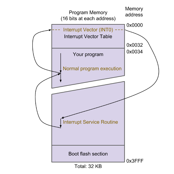
Interrupt Vectors in ATmega328P
At some point, multiple interrupt requests may be called, and the microcontroller must decide which one to treat as the first. Hence, for the microcontroller it is necessary to know which interrupts are preferred over the others.
The microcontroller contains the Interrupt vector table (see Table XXX). This table is at the located at the beginning of the program flash memory and contains the addresses of ISR functions for the individual interrupts. Their numbering reflects their priority – the lower address of interrupt, or number of interrupt vector, the higher priority. From the table, it is apparent that the highest priority has the interrupt RESET and the lowest priority the SPM READY.
| Vector No. | Program Address | Source | Interrupt Definition |
|---|---|---|---|
| 1 | 0x0000 |
RESET |
External Pin, Power-on Reset, Brown-out Reset and Watchdog System Reset |
| 2 | 0x0002 |
INT0 |
External Interrupt Request 0 |
| 3 | 0x0004 |
INT1 |
External Interrupt Request 1 |
| 4 | 0x0006 |
PCINT0 |
Pin Change Interrupt Request 0 |
| 5 | 0x0008 |
PCINT1 |
Pin Change Interrupt Request 1 |
| 6 | 0x000A |
PCINT2 |
Pin Change Interrupt Request 2 |
| 7 | 0x000C |
WDT |
Watchdog Time-out Interrupt |
| 8 | 0x000E |
TIMER2 COMPA |
Timer/Counter2 Compare Match A |
| 9 | 0x0010 |
TIMER2 COMPB |
Timer/Counter2 Compare Match B |
| 10 | 0x0012 |
TIMER2 OVF |
Timer/Counter2 Overflow |
| 11 | 0x0014 |
TIMER1 CAPT |
Timer/Counter1 Capture Event |
| 12 | 0x0016 |
TIMER1 COMPA |
Timer/Counter1 Compare Match A |
| 13 | 0x0018 |
TIMER1 COMPB |
Timer/Coutner1 Compare Match B |
| 14 | 0x001A |
TIMER1 OVF |
Timer/Counter1 Overflow |
| 15 | 0x001C |
TIMER0 COMPA |
Timer/Counter0 Compare Match A |
| 16 | 0x001E |
TIMER0 COMPB |
Timer/Counter0 Compare Match B |
| 17 | 0x0020 |
TIMER0 OVF |
Timer/Counter0 Overflow |
| 18 | 0x0022 |
SPI, STC |
SPI Serial Transfer Complete |
| 19 | 0x0024 |
USART, RX |
USART Rx Complete |
| 20 | 0x0026 |
USART, UDRE |
USART, Data Register Empty |
| 21 | 0x0028 |
USART, TX |
USART, Tx Complete |
| 22 | 0x002A |
ADC |
ADC Conversion Complete |
| 23 | 0x002C |
EE READY |
EEPROM Ready |
| 24 | 0x002E |
ANALOG COMP |
Analog Comparator |
| 25 | 0x0030 |
TWI |
2-wire Serial Interface |
| 26 | 0x0032 |
SPM READY |
Store Program Memory Ready |
: Reset and Interrupt Vectors in ATmega328 and ATmega328P
Handling the External Interrupts with Arduino
Let’s go back to the previous source code, where the polling method was used to detect the motion. This time, we'll try to resolve the issue with interrupt. In particular, we will deal with the external type of interrupt, since the interrupt will be caused by the PIR sensor, which in case of motion, sends the signal to the microcontroller .
Interrupt handling is initialized using the attachInterrupt() function. Initialization can take place anywhere in the program, however if the handling of interrupt in the program does not change, it is good to initialize it in setup() function. This feature has three parameters that tell you what you need to know when handling the interrupts:
- number of interrupt that has to be handled,
- name (or address) of the ISR function that is used to call for its handling, and
- interrupt mode, which defines what behavior on the pin the interrupt causes.
[!NOTE]
Instead of the interrupt number that is to be handled, it is preferable to use the pin number where the interrupt is being monitored. This can be done using the
digitalPinToInterrupt(pin)function, which automatically translates the pin number to the interrupt number. In this way, it is also possible to ensure portability between multiple platforms.
Let's first discover what kind of behavior on the pin will the interrupt cause. Prototyping board Arduino UNO recognizes these four interrupt modes:
LOW- The interrupt is triggered whenLOWlevel is detected on pin. This process occurs, for example, when the button is connected to the digital pin inINPUT_PULLUPmode and, once pressed, theLOWlevel is on the pin.CHANGE- The Interrupt is triggered when the level of pin is changes from eitherHIGHtoLOWor fromLOWtoHIGH. This process takes place, for example, when the switch is pressed.RISING- The interrupt is triggered when the level change fromLOWtoHIGHoccurs. This process takes place, for example, when a button is pressed.FALLING- The interrupt is triggered when the level change fromHIGHtoLOWoccurs. This process takes place, for example, when a pressed button is released.
[!NOTE]
The prototyping boards Arduino Due, Zero and MKR1000 have also the
HIGHmode. This interrupt occurs whenever theHIGHlevel is on the pin.
The each mode is illustrated in the following Figure:

Based on the above stated modes of the interrupts in microcontroller, the following types of external interrupts are:
- Level interrupts - The interrupt is triggered each time a signal of level (
HIGHorLOW) appears on the input. In this type of interrupt, it is good to keep in mind that even though the signal is unchanged, the interrupt may occur repeatedly even during the handling of the previous interrupt. - Edge interrupts - Interrupt is triggered when one level of signal changes to the other (e.g. if the level changes from
HIGHtoLOWorLOWtoHIGH).
Each microcontroller is specific because not every digital pin can be used to capture an external interrupt from a connected device. Hence, it is always necessary to verify the possibilities of the microcontroller in its documentation. In case of Arduino microcontrollers, we can use the Table XXX.
| Board | Digital Pins Usable For Interrupts |
|---|---|
| Uno, Nano, Mini, other 328-based | /2/, /3/ |
| Uno WiFi Rev.2 | all digital pins |
| Mega, Mega2560, MegaADK | /2/, /3/, /18/, /19/, /20/, /21/ |
| Micro, Leonardo, other 32u4-based | /0/, /1/, /2/, /3/, /7/ |
| Zero | all digital pins, except /4/ |
| MKR Family boards | /0/, /1/, /4/, /5/, /6/, /7/, /8/, /9/, /A1/, /A2/ |
| Due | all digital pins |
| 101 | all digital pins (Only pins /2/, /5/, /7/, /8/, /10/, /11/, /12/, /13/ work with CHANGE) |
When comparing the ESP8266 microcontroller, the ATmega 328P is worse, since is it possible to use pins GPIO0 toGPIO15 . This allows simultaneous monitoring of up to 16 different interrupts.
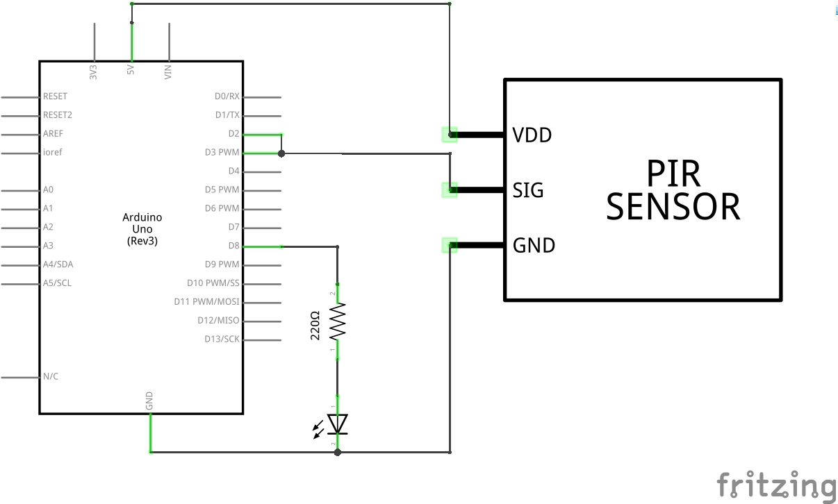
The PIR sensor in the IOT motion detection device is currently connected to pin no. 2. According to the above stated table, it can be used to capture external interrupts.
Consequently, the names of ISR functions have to be known. In the previous case, we used the two functions, named alarm() and idle(). The alarm() function was called when the movement was detected (on the output pin of the PIR sensor the transition was from LOW to HIGH level). The idle() function was called again when the movement vanished (on the output pin of the PIR sensor the transition was from HIGH to LOW level).
Because of this behavior, we can precisely determine in which interrupt mode to call alarm() and in which idle() function:
alarm()will be called inRISINGmodeidle()will be calledFALLINGmode
Thus, the code of setup() function will look like this:
attachInterrupt (digitalPinToInterrupt(PIN_PIR), alarm, RISING);
attachInterrupt (digitalPinToInterrupt(PIN_PIR), idle, FALLING);
Be careful! Each microcontroller contains the Interrupt vectors table (see Table XXX). Each row in this table contains information mapping the ISR function to the source of interrupt. This means that only one ISR function is used to handle the interrupt on one input. There is no information in the record about the mode in which may interrupt occur. Thus, if we used attachInterrupt() function to map two ISR functions for one pin, then we actually overwritten the interrupt handling with the first function using the second function. The code is successfully compiled and started, but the interrupt handling is only executed by the ISR idle() function in the FALLING mode.
Yet, it is still possible to reconfigure the interrupt handling later in the program. As soon as the interrupt occurs and the ISR function is called, part of this function call attachInterrupt() is used for setting the new interrupt handling under different conditions. In this way, the individual ISR functions will redistribute the interrupt handling.
In order to make everything to work properly, it is necessary to apply this information and refactor the setup() function from the previous solution. The global variable isMovement must be labeled using keyword volatile and interrupt handling has to be defined using the ISR function alarm() in RISING mode (motion detection). The updated code of setup() function is in the Listing XXX.
#include <Arduino.h>

#define PIN_LED 8
#define PIN_PIR 2

volatile bool isMovement;

void idle();
void alarm();

void setup(){
    // setup serial
    Serial.begin(9600);
    while(!Serial);

    // set pin modes
    pinMode(PIN_LED, OUTPUT);
    pinMode(PIN_PIR, INPUT);

    // initial state
    isMovement = false;

    // enter idle state
    idle();
}
Then, it is necessary to modify the ISR alarm() and idle() functions. In addition to the original behavior of each, we pre-define the interrupt handling:
- in the case of the ISR
alarm()function, we will define the interrupt handling usingidle()function in theFALLINGmode (from theALARMstate, the device will switch to theIDLEstate, if the change fromHIGHtoLOWlevel occur on pin) - in the case of the ISR
idle()function, we will predefine the interrupt handling using thealarm()function in theRISIGNmode (from theIDLEstate, the device will switch to theALARMstate, if the changes fromLOWtoHIGHlevel occur on pin)
After modification, these functions will be the following:
void idle(){
    Serial.println("> Idle State");

    // update state
    isMovement = false;
    digitalWrite(PIN_LED, LOW);

    // (re)atach interrupt
    attachInterrupt(digitalPinToInterrupt(PIN_PIR), alarm, RISING);
}

void alarm(){
    Serial.println("> Alarm State");

    // update state
    isMovement = true;
    digitalWrite(PIN_LED, HIGH);

    // (re)atach interrupt
    attachInterrupt(digitalPinToInterrupt(PIN_PIR), idle, FALLING);
}
Finally, only the loop() function remains, which is actually empty. The entire code that was used for the pooling solution was moved to ISR functions. We took the advantage of all the benefits offered by the interupts mechanism and removed all the flaws that polling offers. The loop() function therefore leaves the room for own code, which can execute other operations on based on global variable isMovement.
void loop(){
    // nothing to do :-/
}
The complete code is shown in the Listing XXX.
#include <Arduino.h>

#define PIN_LED 8
#define PIN_PIR 2

bool isMovement;

void idle();
void alarm();

void idle(){
    Serial.println("> Idle State");

    // update state
    isMovement = false;
    digitalWrite(PIN_LED, LOW);

    // (re)atach interrupt
    attachInterrupt(digitalPinToInterrupt(PIN_PIR), alarm, RISING);
}

void alarm(){
    Serial.println("> Alarm State");

    // update state
    isMovement = true;
    digitalWrite(PIN_LED, HIGH);

    // (re)atach interrupt
    attachInterrupt(digitalPinToInterrupt(PIN_PIR), idle, FALLING);
}

void setup(){
    // setup serial
    Serial.begin(9600);
    while(!Serial);

    // set pin modes
    pinMode(PIN_LED, OUTPUT);
    pinMode(PIN_PIR, INPUT);

    // initial state
    isMovement = false;

    // enter idle state
    idle();
}

void loop(){
    // nothing to do :-(
}
[!NOTE]
Serial communication inside ISR.
This solution can be further simplified, and it is possible to return to the original concept where the RISING and FALLING interrupts were defined at once. We modify the wiring, connecting the output from the PIR sensor to both pins 2 and 3 at once, while the microcontroller will monitor interrupt RISING on pin 2 and interrupt FALLING on pin 3.
The revised wiring diagram is depicted in Figure XXX, and the updated code is shown in the Listing XXX.
#include <Arduino.h>

#define PIN_LED 8
#define PIN_IDLE 2
#define PIN_ALARM 3

bool isMovement;

void alarm();

void idle(){
    Serial.println("> Idle State");

    // update state
    isMovement = false;
    digitalWrite(PIN_LED, LOW);
}

void alarm(){
    Serial.println("> Alarm State");

    // update state
    isMovement = true;
    digitalWrite(PIN_LED, HIGH);
}

void setup(){
    // setup serial
    Serial.begin(9600);
    while(!Serial);

    // set pin modes
    pinMode(PIN_LED, OUTPUT);
    pinMode(PIN_ALARM, INPUT);
    pinMode(PIN_IDLE, INPUT);

    // initial state
    isMovement = false;

    // atach interrupt
    attachInterrupt(digitalPinToInterrupt(PIN_ALARM), alarm, RISING);
    attachInterrupt(digitalPinToInterrupt(PIN_IDLE), idle, FALLING);
}

void loop(){
    // nothing to do :-(
}
The possibility to use the second pin to monitor the interrupt from another device is not available, however this approach made the code clearer and easier to read. Therefore, specific approach should be always carefully considered.
Turning Interrupts On and Off
Interrupt handling is enabled once the ATmega 328P microcontrollers are turned on. However, they are automatically disabled in the very moment when the interrupt handling occurs using the ISR function and are again automatically enabled once the ISR function is terminated.
There are, however, two macros that can be used to disable and enable interrupt handling globally during the ISR function. These macros are:
interrupts()- globally allows interrupt handlingnoInterrupts()- globally disables interrupt handling
The following part of code illustrates the situation in which we want to re-enable interrupts in the ISR alarm() function:
void alarm(){
    interrupts();
    isMovement = true;
    digitalWrite(PIN_LED, HIGH);
    attachInterrupt(digitalPinToInterrupt(PIN_PIR), idle, FALLING);
}
[!WARNING]
It is necessary to pay close attention, as you may experience unpredictable behavior while utilizing these macros. For example, by enabling interrupt in ISR function, you can achieve a recursive execution of the ISR function when handling the Level interrupts (if the level of signal doesn’t change).
[!NOTE]
In order to globally enable and disable interrupts you can also directly use the AVR
sei()andcli()functions. Thesei()function enables the global interrupts and thecli()function disables global interrupts. Looking more closely to theArduino.hlibrary, it is possible to find out thatinterrupts()andnoInterrupts()macros call just these AVR functions:#define interrupts() sei() #define noInterrupts() cli()However, only the
interrupts()andnoInterrupts()macros will be used in the text due to more readable code.
Handling the Internal Interrupts with Arduino
Timers also fall into the category of the internal interrupts. For example, they allow to set exact start of the part of the program, what is often used to create the impression of "parallelization" of the executed tasks.
The ATmega328P microcontroller contains 3 timers labeled as TIMER0, TIMER1 andTIMER2. TIMER0 andTIMER2 are 8 bit, while TIMER1 is 16 bit timer. Their functionality depends on the microcontroller frequency. In the case of Arduino, an external oscillator with a frequency of 16 MHz is used.
Each timer can generate one or more interrupts. These are:
Compare match interrupt - This type of interrupt occurs when the timer needs to be stopped when a specific value is reached. Its current value is compared to required one, once this occurs, this interrupt will be triggered.
Overflow interrupt - Each timer uses an internal counter that has its range, depending on the size of the used register. The value of the counter is incrementally increased, once the maximum value is reached and it is incremented by one, the overflow occurs and triggers this type of interrupt.
- Input capture interrupt - This type of interrupt is used to capture an event on a pin. The interrupt occurs when a specific edge of the signal is recorded on the pin. It can be rising, falling or any. The timer can record time when this even occurred.
While programming Arduino it is common to use these timers. Timer TIMER0 is used for time functions, such as delay(), millis() and micros(). TIMER1 can also be found in Servo.h library and TIMER2 is used to generate sound using tone() function. The analogWrite() function is used by each timer, but each for different pins.
A summary of available timers properties for the ATmega328P microcontrollers is available in Table XXX.
| Timer | Size | Range | Possible Interrupts |
|---|---|---|---|
TIMER0 |
8 bits | 0-255 | Compare Match, Overflow |
TIMER1 |
16 bits | 0-65535 | Compare Match, Overflow, Input Capture |
TIMER2 |
8 bits | 0-255 | Compare Match, Overflow |
Special timer is Watchdog. If the device gets into an error state, it is its job to reboot the microcontroller after the interval has elapsed. The avr/wdt.h library is available for utilization of Watchdog timer.
TimerOne Library
There are two ways to use timers: using standard AVR libraries or third-party libraries. The very TimerOne library offers a very simple API that covers the low-level access offered by AVR libraries.
This library provides a collection of functions for setting the 16 bit timer called TIMER1 (hence the name of the library). The original intent was to create a simple and quick way to set the PWM period. Yet, the library includes also timer overflow and other properties.
To use with the library, you only need to know the following functions:
Timer1.initialize(microseconds)- This function initializes the timer and must be called as the first. Themicrosecondsparameter defines the timer period.Timer1.attachInterrupt(function)- The ISR function, which name is specified in the parameters, is run every time the period expires.Timer1.detachInterrupt()- Disables the interrupt and the ISR function stops running.
Library also allows to control the already running timer using these functions:
Timer1.start()- Starts the timer and starts a new period.Timer1.stop()- Stops the timer.Timer1.restart()- Restarts the timer from the beginning of the new period.
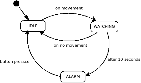
Timers in Motion Detection Scenario
To illustrate the use of timers, we modify the scenario of the developed device for motion detection. A new state called WATCHING is to be added to the existing states. The system will enter this state from the IDLE once the motion is detected. In the WATCHING state, the LED diode turns on and the timer starts. If the movement doesn't stop within next 10 seconds, the system goes to the ALARM state and the LED flashes. However, if there is no movement within these 10 seconds, the diode turns off and the system goes back to the IDLE state. From ALARM you can go to IDLE by pressing the button. The updated status diagram is shown in the Figure XXX.
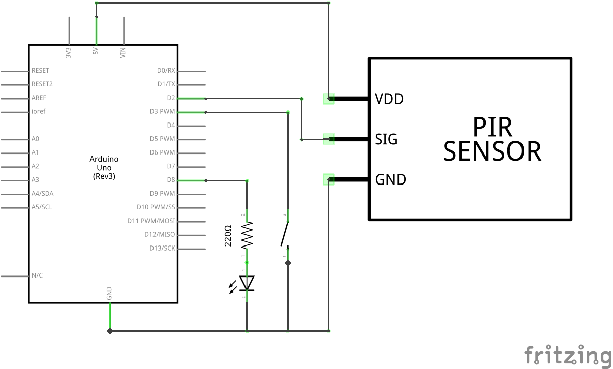
Since the button was added to the system, the wiring diagram is updated and depicted in the Figure XXX.
Changes, of course, were made to the code itself. The setup() function performs a standard initialization, but it also initializes the timer and sets its period to 1 second. From the function, the system gets directly to IDLE.
The newly added function is the watch() function . It sets the 10 second countdown in the countdown variable and sets the ISR tick() function to handle the timer interrupt. Function will be called every second and each time it subtracts 1 from the countdown variable. When it reaches the value of 0, the system enters the ALARM state.
A complete code is shown in Listing XXX.
#include <Arduino.h>
#include <TimerOne.h>

#define PIN_LED 8
#define PIN_PIR 2
#define PIN_BTN 3

volatile bool isMovement;
volatile byte countdown;

void idle();
void watch();
void alarm();

void idle(){
    Serial.println("> Idle State");

    isMovement = false;
    digitalWrite(PIN_LED, LOW);

    // reatach interrupts
    detachInterrupt(digitalPinToInterrupt(PIN_BTN));
    attachInterrupt(digitalPinToInterrupt(PIN_PIR), watch, RISING);
    Timer1.detachInterrupt();
}

void tick(){
    countdown--;
    if(countdown == 0){
        alarm();
    }
}

void watch(){
    Serial.println("> Watch State");

    // update state
    digitalWrite(PIN_LED, HIGH);

    // reatach interrupts
    attachInterrupt(digitalPinToInterrupt(PIN_PIR), idle, FALLING);
    countdown = 10;
    Timer1.attachInterrupt(tick);
    Timer1.restart();
}

void alarm(){
    Serial.println("> Alarm State");

    // update state
    digitalWrite(PIN_LED, HIGH);
    isMovement = true;

    // reatach interrupts
    Timer1.detachInterrupt();
    detachInterrupt(digitalPinToInterrupt(PIN_PIR));
    attachInterrupt(digitalPinToInterrupt(PIN_BTN), idle, LOW);
}

void setup(){
    // set pin modes
    pinMode(PIN_LED, OUTPUT);
    pinMode(LED_BUILTIN, OUTPUT);
    pinMode(PIN_PIR, INPUT);
    pinMode(PIN_BTN, INPUT_PULLUP);

    Serial.begin(9600);
    while(!Serial);

    // setup timer
    Timer1.initialize(1 * 1000000);

    // enter idle state
    idle();
}

void loop(){
    if (isMovement == true){
        digitalWrite(PIN_LED, HIGH);
        delay(1000);
        digitalWrite(PIN_LED, LOW);
        delay(1000);
    }
}
Pros and Cons of Interrupts
Advantages:
- enhanced reaction time when compared to polling
- saving of resources
Disadvantages:
- interrupts are significantly worse to debug because interrupt can occur even during the program debugging. And you suddenly do not know how many interrupts were executed in the current part of the program
Measuring Power when Using Interrupts
- no change