Managing Energy Consumption with Software
Motivation in the Beginning
Imagine that you are working on something very important. You are totally focused, when suddenly your stomach growls and makes variety of sounds to signal you are hungry. You don’t hesitate, it is not the first time you’re becoming hungry, so you call your favorite pizza shop, order your favorite pizza, and the operator will tell you that the pizza will be delivered in 60 minutes. So, for next 60 minutes, you'll be starving.
What now? There are several options to consider:
- I won’t keep working, unless I eat - so I spend the next 60 minutes looking at the watch
- I will continue working and meanwhile will check the watch regularly, waiting for 60 minutes interval to pass
- I will set the alarm clock to notify me after 60 minutes, so I don’t check the watch constantly, and can fully concentrate on the job
Even though this example from the real life seems quite comical, considering the options, we can find some parallels in many of existing IoT solutions. So - what are we doing wrong?
Motion Detection
Initially, we create a simple IoT solution, where the PIR sensor will be used and connected to the microcontroller. This solution will guide us through the whole chapter, where the various approaches to reduce the electricity consumption will be applied.
We will not discuss the functioning of PIR sensor in detail. Simply said, it is a motion sensor, which has 2 inputs (5V power and ground) and 1 output (returns logical 1 (usually at level 3.3V), if the motion is detected, otherwise returns 0). However, for specific values of power and output, you need to check the documentation (datasheet).
[!NOTE]
Of course, the PIR sensor could be used even without a microcontroller. However, we will be interested to find out how to read its output, which says whether or not the motion has occurred.
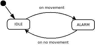
The behavior of the proposed IoT device can be represented by a simple state machine, see the state diagram in the Figure XXX. This machine will always be in one of two states:
IDLE- no motion was detectedALARM- motion was detected

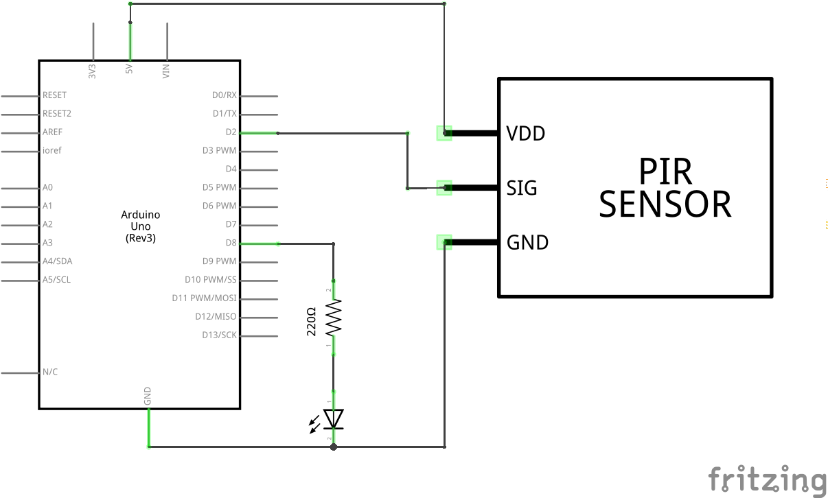
The solution will also include one external LED that will be used to indicate the status of the system. LED can be replaced, for example, by a speaker or any other device that will further process the signal and provide some form of notification, for example in form of SMS message.
The connection diagram of the solution is shown in the Figure XXX.

Let's Code!
The code of setup() function is shown in Listing XXX. As first, two pins are initialized in this function:
- pin 2 - here will be connected output from the PIR sensor, and
- pin 8 - here will be connected notification LED.
Similarly, the global variable isMovement will be initialized to false (no movement) value. This variable will represent the status of the device or system. If motion is detected, its value will be set to true and the system state will change to ALARM. Otherwise, it will be false and the system will be in IDLE state.
Finally, the serial line will be initialized, which will be used for simple logging.
#include <Arduino.h>

#define PIN_LED 8
#define PIN_PIR 2

bool isMovement;

void setup(){
    // setup serial
    Serial.begin(9600);
    while(!Serial);

    // set pin modes
    pinMode(PIN_LED, OUTPUT);
    pinMode(PIN_PIR, INPUT);

    // initial state
    isMovement = false;
}
In the implementation of loop() function, the transition from the IDLE state to the ALARM state, or vice versa, the ALARM state to the IDLE state will occur, based on the reading from the output from the PIR sensor and based on the current state of the system.
void loop(){
    int data = digitalRead(PIN_PIR);

    // state ALARM
    if(isMovement == false && data == HIGH){
        Serial.println("> Alarm State");
        isMovement = true;
        digitalWrite(PIN_LED, HIGH);
    }

    // state IDLE
    if(isMovement == true && data == LOW){
        Serial.println("> Idle State");
        isMovement = false;
        digitalWrite(PIN_LED, LOW);
    }

    // have a break
    delay(500);
}
Once the code is compiled and uploaded to Arduino, the LED diode will turn on or turn off, based on the motion reading from the PIR sensor.
In order for the code to reflect state diagram even more, the states called alarm() and idle() will be created for each state. Each of these will represent the behavior of the system / device in the specific state. This approach will make it easier to navigate in the code and implement further changes.
The code of idle() function is in the Listing XXX. This function turns the LED diode off, sets the value state variable isMovement to false and waits until HIGH reading appears in the output from the PIR sensor.
void idle(){
    Serial.println("> Idle State");

    // update state
    isMovement = false;
    digitalWrite(PIN_LED, LOW);

    // wait for change
    while(digitalRead(PIN_PIR) == LOW){
        delay(500);
    }
}
Then, the alarm() function turns on the LED diode, sets the value of the state variable isMovement to true and waits for the _LOW reading to appear in the output of the PIR sensor. Its code is shown in Listing XXX.
void alarm(){
    Serial.println("> Alarm State");

    // update state
    isMovement = true;
    digitalWrite(PIN_LED, HIGH);

    // wait for change
    while(digitalRead(PIN_PIR) == HIGH){
        delay(500);
    }
}
Finally, we have to adjust the loop() function, which only contains the transition from one state to another. Its code is shown in Listing XXX.
void loop(){
    idle();
    alarm();
}