Managing Energy Consumption with Hardware
Arduino Uno is mainly and foremost a prototyping platform for rapid design and development of solutions. When it comes to the energy conservation it is not very ideal model solution. As was shown in the previous chapter, not only the microcontroller itself, but mainly the board contains components that have a direct impact on energy consumption. In this chapter, we will present particular components as well as their impact on energy consumption.
Arduino Components
Arduino Uno prototyping board can be divided into three main components:
- core or microcontroller
- power supply component
- communication component
The Microcontroller
The core of the board is, of course, the microcontroller ATmega328P. The 328P from the right to left denotes:
Pmeans picoPower. This microcontroller is suitable for the devices with the low consumption.8means that it is 8 bit microcontroller.32means that the microcontroller has available 32kB of program memory.
One of the picoPower architecture attributes is that it allows turning the add-on modules off in order to increase the battery life. These options were illustrated in the previous chapter (such as sleep mode, frequency reduction, etc.). In addition, this microcontroller is characterized by its ability to operate in the voltage range of 1.8V to 5.5V.
Power Supply
If the reference voltage is not considered, the Arduino Uno prototyping board can be powered by two external sources:
- USB port, or
- DC jack
Supply via USB port is directly applied to the board. This means that if you accidentally provide a higher voltage than 5V (the maximum allowed voltage is 5.5V), you can actually destroy the Arduino. The voltage regulators are behind the DC jack. These are used to ensure that the maximum supply voltage (max. 20V) of 5V is provided to the board.
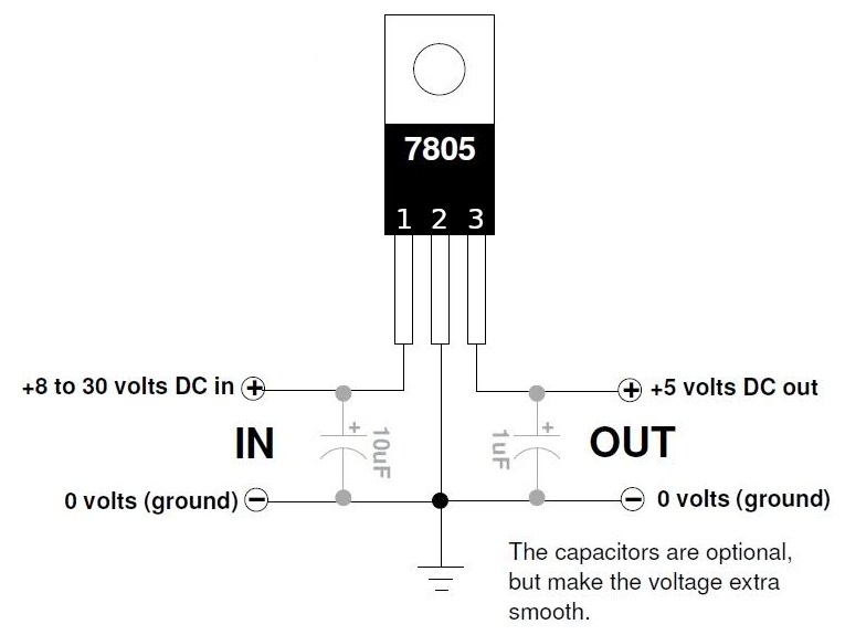
The stabilizer used on the Arduino Uno prototyping board is standard LM7805 1. This stabilizer has been used for many years to stabilize the supply voltage to 5V. On the input it requires the voltage of at least 7V and for its own use it consumes 5 to 8 mA. However, the higher the voltage, will be brought to the input of the stabilizer, the greater the losses will occur. Excessive energy is converted to heat, which means that the stabilizer will overheat at higher voltages. Therefore, it is good to power the Arduino Uno using a DC jack with a voltage close to 7V.
Power that is converted to the heat can be easily calculated using the following relationship:
From this relationship follows exactly what is stated above - larger the difference between the input and output voltages, greater the losses (in form of the heat).
The principal circuit diagram for connection of the LM7805 stabilizer is depicted in Figure XXX.
There are stabilizers referred to as LDO (Low Drop-Out) or Ultra LDO, which require significantly lower current when compared to the LM7805 stabilizer. Take for example MCP1703 stabilizer 2 that has voltage drop of 1V and for its consumption needs 2 microamperes (parameter labeled as Quiescent Current). Stabilizers from theTPS783xx series3 have voltage drop of approx. 150mV and own consumption of 500nA.
Enhancing the energy consumption of the IoT device, built on the Arduino Uno prototyping board, would be possible by replacement of the stabilizer. However, since the stabilizer is a fixed part of the board, this is not possible.
Communication Part
The Arduino Uno prototyping board is equipped with an ATmega16U2 chip, which serves as a converter between the USB and the serial line. It is used both, for communication between the Arduino board and connected devices, but also for the programming of the ATmega328P microcontroller.
If the Arduino Uno is powered from the USB port, of course no losses occur. However, the chip doesn’t provide any energy conservation measures. This means that even if there is no communication on the serial line, the chip will still consume the electricity. Disconnecting it in such a state would allow to rapidly reduce the consumption of the entire board.
1. LM7805 Datasheet - https://www.sparkfun.com/datasheets/Components/LM7805.pdf ↩
2. MCP1703 Datasheet - http://ww1.microchip.com/downloads/en/devicedoc/22049e.pdf ↩
3. TPS783xx Datasheet - http://www.ti.com/lit/ds/symlink/tps783.pdf ↩